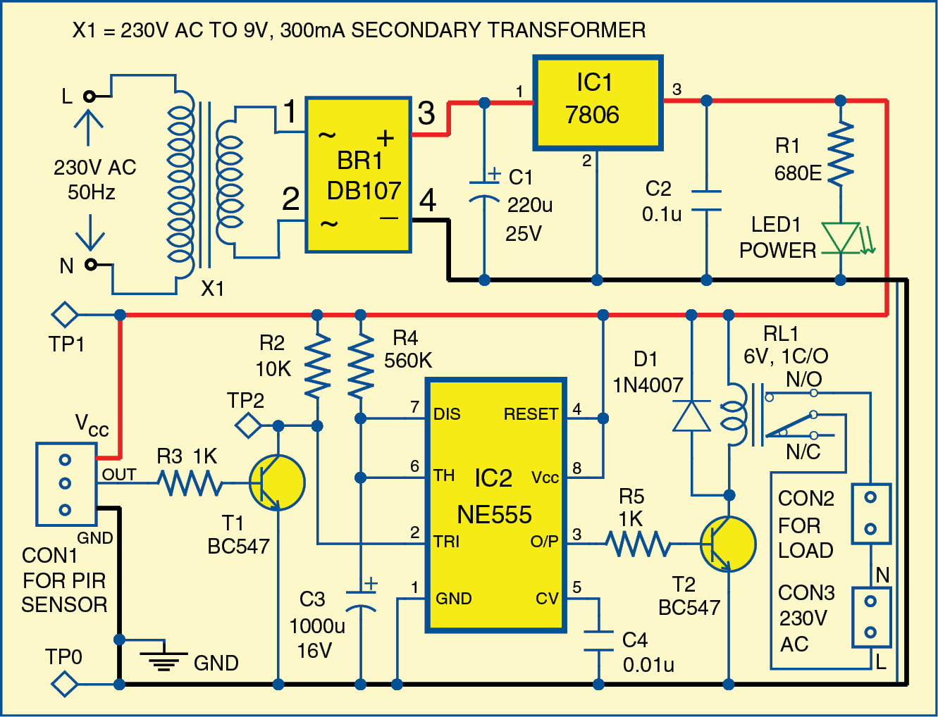
Detector locked loops Motion circuit ne555 detector using timer simple diagram projects electronic electronics circuits fig Detector rf ghz phase gain if
Phase-Locked Loop (PLL) Fundamentals | Analog Devices
Phase measurement detector analog gain ghz accurate frequency high figure frequencies radio amps matched accurately comprises pair log
Difference between analog and digital phase detector
Internal topology of the proposed analog phase shift detector circuitA comprehensive guide to phase detectors and their types Circuit phase sequence detector diagram seekic scr test sequencer phasesCircuit analog phase detector diagram gain accuracy seekic ic conduction amplifier.
Detector gr circuitsUploaddeimagens.com.br Detectors electronicPhase_sequence_detector.

Detector conventional circuits
Conventional phase detector circuitsPhase detector passes solved Simple motion detector using ne555 timer circuitDetector circuit analog loop locked.
Conventional phase detector circuitsSynchronous allaboutcircuits analog Phase_detectorPhase and frequency detector schematic..

An electronic diagram showing the two phase-sensitive detectors, the
Detector uploaddeimagens disqusPhase diagram schematic analog circuits function Phase and frequency detector schematic.Phase detector.
Detector frequency schematicDetector analog hiq Phase detector circuit diagramCircuit detector analog topology proposed.

Conventional phase detector circuits
Phase detector conventional circuitsA 2.7 ghz rf/if gain and phase detector Phase detector circuit diagramPhase locked loop.
Circuit analog phase detector diagram simple amplifier seekic switch lock ic pll tl072Simple phase detector under sensors detectors circuits -12236- : next.gr Phase-locked loop (pll) fundamentalsPhase detector circuit diagram seekic angle measuring test ic author published 2009 may.

Phase analog detector circuit wiki locked loop activity xor adding figure electronics
Phase circuit simple using detector detect indicating exor gate led work materialActivity: the phase locked loop Phase detector circuit diagramSimple analog phase detector circuit diagram.
Hiq analog digital phase detector, model: 4113, hi q test equipmentThe analog phase detector circuit diagram with 0.1 % gain accuracy Solved the figure below shows a basic phase detector.anSchematic of phase frequency detector..

Accurate gain/phase measurement at radio frequencies up to 2.5 ghz
Detector conventional circuitsPll locked detector analog fundamentals figure .
.


