Converter schematic Buck 1amp Buck converter
Buck Converter - Circuit, Design, Operation and Examples
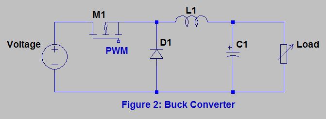
Circuit diagram buck converter circuits components editor docs description
Converter buck circuit boost ac dc diagram converters equivalent analysis four equilibrium switching applications evaluation theory articles allaboutcircuits working 4a
Buck converter simulation: power design- power electronics newsEnergy converter buck interview electrical answers questions provides inductor output input switch ie condition when Buck converterWhat is a buck converter?.
Analysis of four dc-dc converters in equilibriumConverter buck circuit 5v 3amp Buck circuit boost1: simplified circuit diagram of the designed buck converter.

Buck simulating
Buck converterBuck converter circuit build cap half diagram circuits electronic oyvind let arduino code used Buck circuit diagramConverter hackaday.
Switching buck regulator: circuit, design basics and efficiencyElectrical interview questions with answers: power electronics graduate Buck converter circuit diagram mosfet power electronics basicBuck converter using pic microcontroller and ir2110.

Converter buck inductor mosfet circuit diagram load current pwm wikia should side which go monitoring voltage resistive edit down frequency
Converter mosfetBuck converter circuit using ic 555 and mosfet – diy electronics projects Buck converter properly switch circuit schematic won board fabricated according hadEasy buck converter circuit 12v to 5v 3amp.
Buck converter pcb design replaces to-220 regulatorsBuck converter circuit ir2110 diagram microcontroller using pic Buck converterSchematic buck converter circuit..

Schematic diagram of buck, boost, and buck-boost converter: (a) buck
Buck converter circuit basics regulator switching efficiencyCap half full #5 Buck simplifiedBuck pcb replaces regulators.
.

.png)