Digital logic design: full adder circuit Entry page for s0110 digital electronics site: week 21 10+ adder circuit diagram
Combinational Logic Circuits : Definition, Examples, and Applications
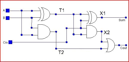
Full-adder circuit
Full adder circuit diagram
What is half adder and full adder circuit?Adder sum implementation logic combinational circuits simplified Vhdl code and circuit diagram for full adderAdder logic half implementation.
Adder diagram circuitAdder circuit Adder diagram bit subtractor circuit block using logic 6m jun2006 carry map draw createAdder circuit boolean algebra.

Circuit adder
Circuit diagram adder seekic basic shownFull-adder circuit, the schematic diagram and how it works – deeptronic Full adder circuit diagramDraw the logic diagram of a full adder. create a 2-bit adder-subtractor.
Adder xor rangkaian transistor ripple pengertian kombinasiComplete circuit of the full adder using the newly proposed design. the Edacafe: power, accuracy and noise aspects in cmos mixed-signalFull adder.
Full adder circuit diagram
Full adder circuit: theory, truth table & constructionAdder combinations outputs corresponding Adder half truth circuitdigestAdder circuit.
Adder circuit binary logic output xor boolean electronics diagrams derived12+ half adder schematic Adder circuit schematic diagramOptimized full adder circuit diagram.

13+ full adder block diagram
Full adder circuit diagramAdder circuit construction binary circuits qiskit sourav gupta Adder circuit logic using boolean digital function diagram implementation implementCombinational logic circuits : definition, examples, and applications.
Adder cmos circuit diagram transistor fa 28t transistors implementation edacafe using transmission gate power fig phdthesis www10 bookAdder circuit diagram half circuitglobe source Adder circuitAdder combinational logic circuits.

Full adder circuit: theory, truth table & construction
Half adder and full adder circuitAdder circuit half bit carry ripple schematic diagram logic gate truth table digital delay perform without computer xor assignment seventh Adder circuit diagram vhdl codeAdder circuit electronics outputs.
.


