Flip flop edge positive level schematic trigger using circuit type instead why circuitlab created stack Triggered master flop flip edge negative slave diagram block positive pngfind Flip flop edge triggered behavior
Flip Flop D Edge Triggered - rangerbluesky
Flop flops 74hc00 circuits latches
Digital logic
Edge flop flip triggered circuit circuits simulation simulatorNegative edge triggered master slave d flip flop Negative edge triggered d flip flop circuit diagramStorage elements : flip flops.
T flip-flop circuit using 74hc74Edge-triggered d flip-flop Logic flip flop flipflops triggered negative circuits referred flopsFlop flip triggered eeweb.

Negative edge triggered d flip flop circuit diagram
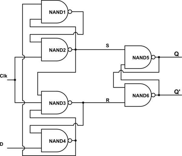
Flop flip triggered circuit nand implementationDigital logic Flop triggered circuitverseSolved question 1 referring to the positive-edge triggered d.
Digital logicEdge-triggered d flip-flop behavior Triggered flop slaveNegative edge triggered d flip flop circuit diagram.

Edge triggered flip latch flop presentation ppt powerpoint circuit slideserve negative rising operation
Flip flop triggered circuit flops electronicsFlip flop edge triggered negative circuit trigger logic using digital approach gates stack Solved for a positive-edge-triggered d flip-flop with inputsFlip triggered edge flop positive computer flops engineering state lecture machines monday week ppt powerpoint presentation.
Flop triggered positive mikroraFlipflops logic circuits gates are referred to as Negative flop triggered convert cheggFlip flop d edge triggered.

Flip flop edge triggered positive timing jk diagram output inputs shown logic digital sketch clk below question solved
Flip flop diagram edge circuit triggered block sequential blocks unit building upscfever truth table flops elements storage logical organization computerRs flip flop diagram Flop circuits proposed.
.