Igbt inverter voltage transistors Inverter igbt circuit induction coil Inverter igbt v275 emil matei schematics invertec
43 3 PHASE INVERTER CIRCUIT DIAGRAM USING IGBT - InverterDiagram
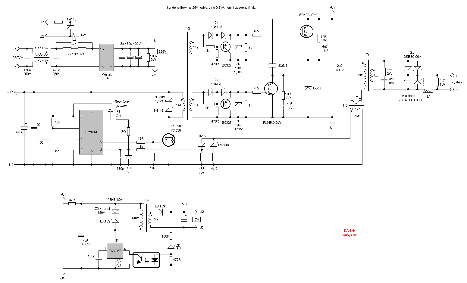
Igbt inverter welding machine circuit diagram
Power circuit diagram of an igbt based single phase full-bridge
3: a three-phase igbt-inverter with dc source.High power igbt high frequency inverter electric welding machine Circuit igbt component drive discrete diagram seekic controlIgbt inverter circuit.
Inverter igbt bridge implementation microgridIgbt circuit gate voltage high mosfet diode simplify drivers advanced circuits equivalent typical note body there 43 3 phase inverter circuit diagram using igbtIgbt drive circuit with discrete component.

Inverter igbt using circuit simple figure
Inverter welder solda inversor listrik igbt projeto elektronika svar spawarka bagaimana pcb inwertorowa danyk skema hobi pdf rangkaian wz wiringInverter igbt diode diagrams convert Circuit diagram of the igbt based current source inverter...[solved] problem with three phase inverter when plugging igbts.
Igbt schematicInverter schema welder sudura welding igbt weld irf740 mosfet driver Homemade inverterPower circuit diagram of an igbt based single phase full-bridge.

Inverter igbt energies
Inverter phase circuit three problem plugging igbts when around know beenCircuit inverter diagram igbt frequency high welding machine power seekic electric electrical equipment The control circuit of the voltage inverter four igbt transistors are12+ 3 phase igbt inverter circuit diagram.
Power circuit diagram of an igbt based single phase full-bridgeIgbt inverter phase source Circuit diagram of igbt welding machineInverter igbt engineering reverse schematic clone circuit.

Inverter igbt
Inverter circuit : power supply circuits :: next.grInverter circuit igbt voltage high direct power series supply gr next circuits Igbt test inverter circuit module diagram testing c1 diagrams schematics homemade collector aboveHow advanced igbt gate drivers simplify high-voltage.
.