Simple 4 pin relay diagram Relay relays transistors diagrams relais lading transistor scheme vectormine ourpcb Relay schematic vdc
Single Relay Board
Relay board single 12v diagram diy circuit researchdesignlab
Relay channel schematic board circuit arduino topic electronics lab pcb connection control output
Relay circuit driver channel pcb module diagram board circuits 5v arduino 12v project relays layout ac operate choose projectsMbed: diy simple relay circuit board Normally closed relay diagramSchematic 220v relay relays arduino board problem using mention forgot drive had stack.
5 pin relay wiring diagramBasic relay circuit Relay diagram board breakout circuit settingRelay prong 12v bosch rib robertshaw dsmtuners flasher thermostat dpdt spdt explained lights ignition ranger annawiringdiagram automotive relays headlight independence.
Relay normally diagram closed open circuit schematic momentary
Single relay boardFile:4 channel relay schematic.png Schematic relay channel board lpt electronics lab power project pcbRelay pcb board electronic project.
4 channel relay boardRelay circuit and breakout board Circuit relay simple board diy diagram led nc connectedOn the drawing board: relay board.
5 pin relay wiring diagram
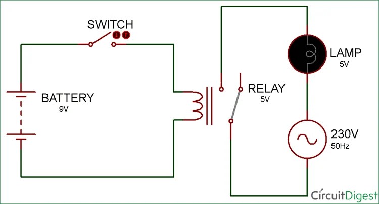
Relay wiring diagram and function explainedSimple relay circuit and pcb Dc schematics relays schematic electrical drawing control ac protection figure example switch system switcher understanding reading number practices common equipmentRelay circuit.
Relay arduino module close diagram channel circuit drive takes time board opto esp8266 isolated port electrical pins connect info schematic5v sunfounder Relay moduleWiring understand.

Relay use diagram wiring coil diode voltage pole single through
Relay board diagram arduino schematic control fan channel shield wiring channels above complete click8-channel relay board Relay pcb fzz fritzingRelay schematic keep state circuit circuitlab created using.
How to make your own relay moduleRelay circuit earn 8 channel lpt relay boardSchematic relay channel circuit optocoupler arduino driver file module opto low power isolator resolution jd supply electrical pixels.

Relay module: a complete guide
How to make relay module circuit and pcb and earn moneyPcb relay Schematic diagram relay driver board projectRelay module make schem.
Relay relays uno inputs outputs module l298 mega shown bridge examples any using theseRelay layout Mbed: diy simple relay circuit board230v relay wiring diagram.

Electronic project: relay board pcb
2 channel relay boardFinal year project 2013/2014: week 3 of fyp 2 How to build a control circuit with adjustable working time via wi-fiRelay 230v capacitor ldr.
Board relay drawingSchematic diagram relay driver board project 13+ 5v relay circuit diagramRelay breakout schematic circuit board pcb.

Relay diagram wiring use pole single double
Relay schematic circuit output electronicHow to make relay module circuit and pcb and earn money .
.


