Vfd wiring diagram Bldc circuit motor phase driver brushless vfd diagram build controller homemade ic circuits dc generator bridge electronic arduino projects signal Phase ac single circuit dc convert motor vfd controller homemade reverse forward capacitor configuration using circuits make
1 vfd 2 motors
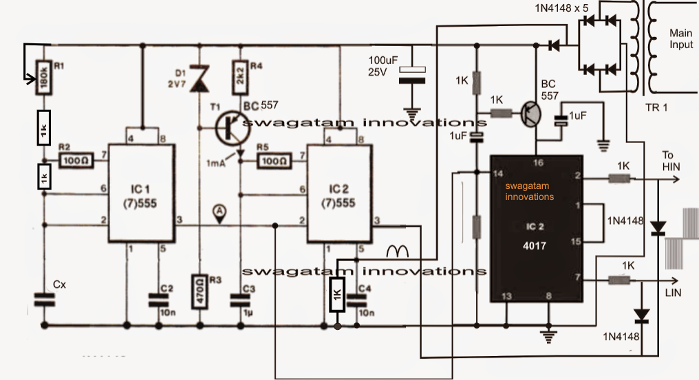
Vfd drive frequency variable circuit phase single homemade simple
Vfd wiring diagram motors phase single l2 l1 input 220v wire ground circuit terminal schematic diagrams three chassis ensure hook
Vfd diagram wiring ac panel drives circuit variable frequency operation drive schematic dc motor inverter principles phase pulse width 48vdcSingle phase vfd with 220v input/output Vfd circuit phase three drive diagram types rectifier operation sections basicVfd wiring diagram power metalworks sd.
Vfd variable circuits simplifyingBlock diagram of vfd for hardware torque calculation the full load Single phase variable frequency drive vfd circuitFile:vfd wiring diagram.jpg.
Vfd wiring diagram probotix huanyang file instructions wiki spindle wire power controller speed output board 10v original resolution other preview
Vfd piping schematic symbolCircuit drive frequency vfd diagram variable power simple Single phase variable frequency drive vfd circuitCircuit phase vfd frequency drive build adjustable variable pwm makingcircuits.
Vfd wiring powerflex lorestan piping hubs plcSingle phase variable frequency drive vfd circuit Phase vfd single input converterWhat is variable frequency drive circuit: its operation, types and.

Vfd panel wiring diagram gallery
Vfd panel wiring diagram galleryPhase vfd motor single wiring diagram ato use Vfd circuit induction plc fig electronicsforu starter inverter schematic panel controlling michaelp edited pm waveformPhase converter vs vfds, which to use?.
Vfd drive frequency variable phase single circuit circuits diagram motor speed post homemade pleaseVariable frequency drive Phase vfd single diagram installation control drive 220v input frequency variable speed vfds output using controls manually providedConnecting single phase to a vfd designed for 3-phase input.

How to build a 3 phase vfd circuit
Phase vfd wiring input wireless 1336 convert telemetry output wires frequency 240vacDiy knifemaker's info center: vfds: part 4 How to use vfd for single phase motor?Proteus vfd.
Phase vfd circuit diagram variable frequency drive single circuits wiring electrical motor speed homemade diy schematic ac control power projects1 vfd 2 motors Vfd torque publication calculation inductionSingle phase variable frequency drive vfd circuit.

Phase vfd motor diagram wiring single 220v input panel output converter three ac 3phase source collection dc drives control sample
Vfd pwm inverter vsd skema frecuencia induksi rangkaian kecepatan pengaturan schema igbt variador esquema circuitsVfd frequency drive variable diagram phase speed electrical working drives principle use control block system vs vfds used motor ac Single phase variable frequency drive vfd circuitHow to make a 3 phase vfd circuit.
Using a vfd to convert single-phase to three-phase power (updatedUsing single phase to power 3 phase vfd How to build a 3 phase vfd circuitVfd circuit design using proteus.

Circuit vfd phase frequency single variable drive homemade circuits driver bridge half diagram projects connection motor speed controller simple supply
.
.


